
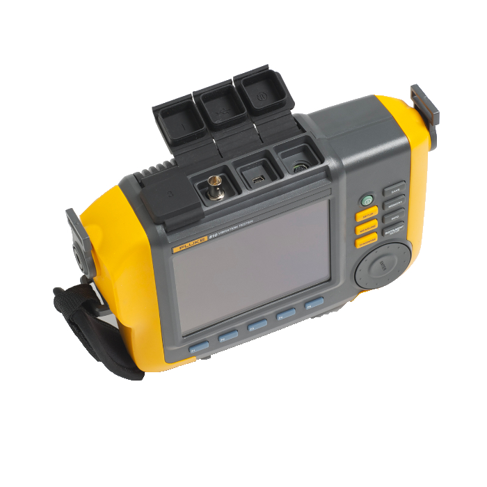

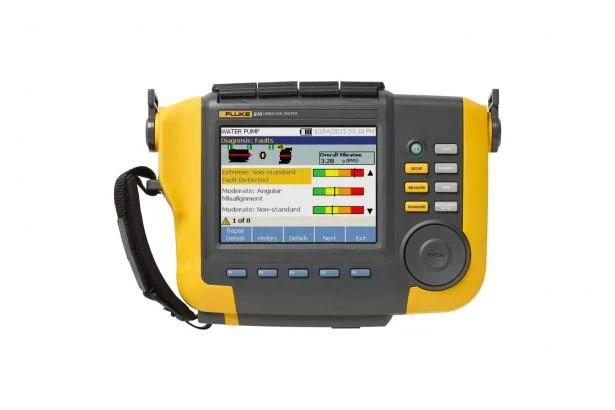
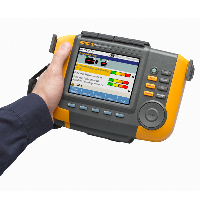
Fluke 810 Vibration Tester
$ 8499.00
$ 13299.00
📦 Product Description: Fluke 810 Vibration Tester
Take full control of your machinery maintenance with the Fluke 810 Vibration Tester, the ultimate tool for diagnosing mechanical issues before they cause costly downtime.
✅ Key Features:
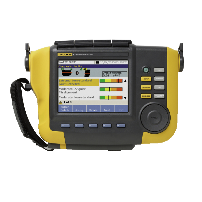
Instant Diagnostics: Identifies common mechanical faults such as bearing wear, misalignment, imbalance, and looseness—no prior vibration history needed.
Severity Scale: Prioritize repairs with a clear 4-level fault severity rating.
On-Screen Repair Recommendations: Guides technicians on corrective actions in real-time.
Spectral Diagrams & Detailed Reports: Validate data quality and pinpoint root causes quickly.
Built-in Help: Context-sensitive tips assist new users during testing.
🔧 Use Cases:
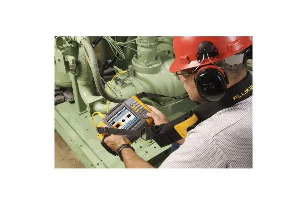
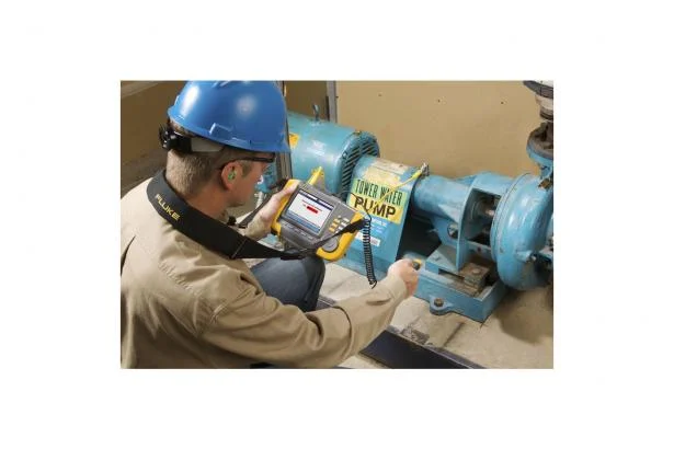
Troubleshoot failing equipment fast and accurately
Verify machine condition before/after repairs
Commission new installations and validate setup
Prevent breakdowns and plan spare parts inventory
Train your maintenance team with hands-on diagnostics
🛠 Why Choose the Fluke 810:
It’s like having a vibration analysis expert in your toolbox. Whether you're fighting recurring failures or setting repair priorities under pressure, the 810 gives you the answers now—right on site.
Specifications: Fluke 438-II Power Quality Analyzer & Motor Analyzer
Amps (accuracy excluding clamp accuracy)
Drive Measurement DetailsVariable speed drive technology that is covered by the 438-IIVariable speed drive technology NOT covered by the 438-IIMechanical specificationsMotor measurementProduct SpecificationsHzPowerEnergyHarmonicsFlickerUnbalanceMains SignalingGeneral SpecificationsEnvironmental| Motor Type | 3 phase asynchronous (induction) | |||
| Power Source | Variable Frequency Drive | |||
| Motor Frequency Range | 40Hz to 70Hz | |||
| Over/Under Voltage from Nominal V/f Curve (%) | -15% to +15% | |||
| Carrier Frequency Range | 2.5kHz–20kHz | |||
| Inverter Type | VSI only (voltage controlled) * | |||
| Control Method | V/f control, open-loop vector, closed loop vector, drives with encoders. | |||
| Frequency | 40 to 70 Hz | |||
| * VSI drives are the most common drives. The alternative CSI drives are used in higher power applications. | ||||
| Inverter Type | CSI (current source inverter) | |||
| Motors type | Synchronous (DC, stepper, permanent magnet etc.) | |||
| Motor Frequency | <40 and >70 Hz | |||
| Mechanical measurements can be performed on direct online motors with a 3 wire connection. | ||||
| Range | Resolution | Accuracy | Default limit | |
| Mechanical motor Power | 0.7 kW to 746 kW 1 hp to 1000 hp | 0.1 kW 0.1 hp | ±3% 1 ±3% 1 | 100% = rated power 100% = rated power |
| Torque | 0 Nm to 10 000 Nm 0 lb ft to 10 000 lb ft | 0.1 Nm 0.1 lb ft | ±5% 1 ±5% 1 | 100% = rated torque 100% = rated torque |
| rpm | 0 rpm to 3600 rpm | 1 rpm | ±3% 1 | 100% = rated rpm |
| Efficiency | 0% to 100% | 0.10% | ±3% 1 | NA |
| Unbalance (NEMA) | 0% to 100% | 0.10% | ±0.15% | 5% |
| Harmonics Voltage Factor (NEMA) | 0 to 0.20 | 0.1 | ±1.5% | 0.15 |
| Unbalance Derating Factor | 0.7 to 1.0 | 0.1 | indicative | NA |
| Harmonics Derating Factor | 0.7 to 1.0 | 0.1 | indicative | NA |
| Total NEMA Derating Factor | 0.5 to 1.0 | 0.1 | indicative | NA |
| Notes: | Supports motor design types NEMA A, B, C, D & E and IEC type H and N. Rated torque is calculated from rated power and rated speed. Update rate of Motor Measurements is 1x per second. Default Trend duration is 1 week. | |||
| 1Add 5% error when selecting Motor design type Other Specification valid for Motor Power > 30% of rated power Specification valid at stable operating temperature. Run the motor for at least 1 hour at full load (2-3 hours if the motor is 50 HP or higher) to obtain stable temperature | ||||
| Volt | Model | Measurement Range | Resolution | Accuracy |
| Vrms (AC + DC) | 1 V to 1000 V phase to neutral | 0.01 V | ±0.1% of nominal voltage 1 | |
| Vpk | 1 Vpk to 1400 Vpk | 1 V | 5% of nominal voltage | |
| Voltage Crest Factor (CF) | 1.0 > 2.8 | 0.01 | ±5% | |
| Vrms½ | 0.1 V | ±0.2% of nominal voltage | ||
| Vfund | 0.1 V | ±0.1% of nominal voltage | ||
| Amps (AC + DC) | i430-Flex 1x | 5 A to 6000 A | 1 A | ±0.5% ±5 counts |
| i430-Flex 10x | 0.5 A to 600 A | 0.1 A | ±0.5% ±5 counts | |
| 1mV/A 1x | 5 A to 2000 A | 1A | ±0.5% ±5 counts | |
| 1mV/A 10x | 0.5 A A to 200 A (AC only) | 0.1 A | ±0.5% ±5 counts | |
| Apk | i430-Flex | 8400 Apk | 1 Arms | ±5% |
| 1mV/A | 5500 Apk | 1 Arms | ±5% | |
| A Crest Factor (CF) | 1 to 10 | 0.01 | ±5% | |
| Amps½ | i430-Flex 1x | 5 A to 6000 A | 1 A | ±1% ±10 counts |
| i430-Flex 10x | 0.5 A to 600 A | 0.1 A | ±1% ±10 counts | |
| 1mV/A 1x | 5 A to 2000 A | 1 A | ±1% ±10 counts | |
| 1mV/A 10x | 0.5 A A to 200 A (AC only) | 0.1 A | ±1% ±10 counts | |
| Afund | i430-Flex 1x | 5 A to 6000 A | 1 A | ±0.5% ±5 counts |
| i430-Flex 10x | 0.5 A to 600 A | 0.1 A | ±0.5% ±5 counts | |
| 1mV/A 1x | 5 A to 2000 A | 1 A | ±0.5% ±5 counts | |
| 1mV/A 10x | 0.5 A A to 200 A (AC only) | 0.1 A | ±0.5% ±5 counts | |
| Fluke 434 @ 50 Hz Nominal | 42.50 Hz to 57.50 Hz | 0.01 Hz | ±0.01 Hz | |
| Fluke 434 @ 60 Hz Nominal | 51.00 Hz to 69.00 Hz | 0.01 Hz | ±0.01 Hz | |
| Watts (VA, var) | i430-Flex | max 6000 MW | 0.1 W to 1 MW | ±1% ±10 counts |
| 1 mV/A | max 2000 MW | 0.1 W to 1 MW | ±1% ±10 counts | |
| Power Factor (Cos j/DPF) | 0 to 1 | 0.001 | ±0.1% @ nominal load conditions | |
| kWh (kVAh, kvarh) | i430-Flex 10x | Depends on clamp scaling and V nominal | ±1% ±10 counts | |
| Energy Loss | i430-Flex 10x | Depends on clamp scaling and V nominal | ±1% ±10 counts Excluding line resistance accuracy | |
| Harmonic Order (n) | DC, 1 to 50 Grouping: Harmonic groups according to IEC 61000-4-7 | |||
| Inter-Harmonic Order (n) | OFF, 1 to 50 Grouping: Harmonic and Interharmonic subgroups according to IEC 61000-4-7 | |||
| Volts % | f | 0.0% to 100% | 0.1% | ±0.1% ±n x 0.1% |
| r | 0.0% to 100% | 0.1% | ±0.1% ±n x 0.4% | |
| Absolute | 0.0 to 1000 V | 0.1 V | ±5% 1 | |
| THD | 0.0% to 100% | 0.1% | ±2.5% | |
| Amps % | f | 0.0% to 100% | 0.1% | ±0.1% ±n x 0.1% |
| r | 0.0% to 100% | 0.1% | ±0.1% ±n x 0.4% | |
| Absolute | 0.0 to 600 A | 0.1 A | ±5% ±5 counts | |
| THD | 0.0% to 100% | 0.1% | ±2.5% | |
| Watts % | f or r | 0.0% to 100% | 0.1% | ±n x 2% |
| Absolute | Depends on clamp scaling and V nominal | — | ±5% ±n x 2% ±10 counts | |
| THD | 0.0% to 100% | 0.1% | ±5% | |
| Phase Angle | -360° to +0° | 1° | ±n x 1° | |
| Plt, Pst, Pst (1 min) Pinst | 0.00 to 20.00 | 0.01 | ±5% | |
| Volts % | 0.0% to 20.0% | 0.1% | ±0.1% | |
| Amps % | 0.0% to 20.0% | 0.1% | ±1% | |
| Threshold Levels | Threshold, limits and signaling duration is programable for two signaling frequencies | — | — | |
| Signaling Frequency | 60 Hz to 3000 Hz | 0.1 Hz | ||
| Relative V % | 0% to 100% | 0.10% | ±0.4% | |
| Absolute V3s (3 second avg.) | 0.0 V to 1000 V | 0.1 V | ±5% of nominal voltage | |
| Case | Design Rugged, shock proof with integrated protective holster Drip and dust proof IP51 according to IEC60529 when used in tilt stand position Shock and vibration Shock 30 g, vibration: 3 g sinusoid, random 0.03 g 2 /Hz according to MIL-PRF-28800F Class 2 | |||
| Display | Brightness: 200 cd/m 2 typ. using power adapter, 90 cd/m 2 typical using battery power Size: 127 x 88 mm (153 mm/6.0 in diagonal) LCD Resolution: 320 x 240 pixels Contrast and brightness: user-adjustable, temperature compensated | |||
| Memory | 8GB SD card (SDHC compliant, FAT32 formatted), up to 32GB optionally. Screen save and multiple data memories for storing data including recordings (dependent on memory size). | |||
| Real-Time Clock | Time and date stamp for Trend mode, Transient display, System Monitor and event capture | |||
| Operating Temperature | 0°C ~ +40°C; +40°C ~ +50°C excl. battery | |||
| Storage Temperature | -20°C ~ +60°C | |||
| Humidity | +10°C ~ +30°C: 95% RH non-condensing +30°C ~ +40°C: 75% RH non-condensing +40°C ~ +50°C: 45% RH non-condensing | |||
| Maximum Operating Altitude | Up to 2,000 m (6666 ft) for CAT IV 600 V, CAT III 1000 V Up to 3,000 m (10,000 ft) for CAT III 600 V, CAT II 1000 V Maximum storage altitude 12 km (40,000 ft) | |||
| Electro-Magnetic-Compatibility (EMC) | EN 61326 (2005-12) for emission and immunity | |||
| Interfaces | Mini-USB-B, Isolated USB port for PC connectivity SD card slot accessible behind instrument battery | |||
| Warranty | Three years (parts and labor) on main instrument, one year on accessories | |||
| View full family specifications » | ||||
| 1. ±5% if ≥ 1% of nominal voltage ±0.05% of nominal voltage if < 1% of nominal voltage 2. 50Hz/60Hz nominal frequency according to IEC 61000-4-30 3. 400Hz measurements are not supported for Flicker, Mains Signaling and Monitor Mode 4. For nominal voltage 50 V to 500 V | ||||
Fast & Reliable Shipping
We provide quick and dependable shipping with tracking included on all orders. Get real-time updates and enjoy peace of mind knowing when your product will arrive.
Secure Payments & Buyer Protection
Your security is our top priority. We use industry-leading encryption and trusted payment processors to ensure your personal and payment information remains completely safe. Shop with confidence knowing that your data is fully protected.
30 Days Money-Back Guarantee
All products displayed in our store are subject to an exchange and refund policy in accordance with the terms and conditions shown on this page.
Authorized Dealer
We are an official seller of all the products listed on our website. You will receive 100% authentic and manufacturer-approved products, backed by warranties and excellent support.